WORTH READING /

Cockpit Display Systems: From Glass Panels to Mission-Ready Avionics

Cockpit display systems are among the most critical interfaces in modern aviation. Whether guiding a commercial airliner through low-visibility approaches or supporting a military crew in a high-threat environment, the display suite in the cockpit is the aircrew’s primary window into the state of the aircraft and mission. Understanding what these systems are, how they work, and what standards govern them is essential for engineers, procurement managers, and system integrators who specify and source avionics display systems for new platforms and upgrade programs.

What Is a Cockpit Display System?
A cockpit display system is an integrated set of electronic screens and associated processing hardware that presents flight, navigation, engine, and mission data to the flight crew. Unlike legacy analog instrument panels – filled with individual gauges and dials – modern glass cockpit displays consolidate this information onto multi-function screens, dramatically reducing pilot workload and improving situational awareness. The shift from electromechanical instruments to digital cockpit displays represents one of the most transformative advances in aviation history, beginning in the 1980s and accelerating through the present day.

Core Components of a Modern Cockpit Display Suite
A complete aircraft cockpit display installation typically comprises several interdependent elements:

  • Primary Flight Display (PFD): The primary flight display presents attitude, airspeed, altitude, vertical speed, and heading on a single screen, replacing six or more conventional instruments.
  • Multi-Function Display (MFD): The multi function cockpit display shows navigation maps, terrain, weather radar, traffic, and system synoptics. Crews can reconfigure the MFD to prioritize the data most relevant to the current phase of flight or mission.
  • Engine Indication and Crew Alerting System (EICAS / ECAM): Monitors propulsion and aircraft systems, presenting warnings and checklists to the crew.
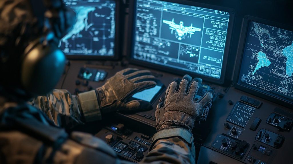
  • Head-Up Display (HUD): Projects flight-critical symbology onto a combiner glass at the pilot’s eye level, enabling eyes-out situational awareness during critical maneuvers.
  • Display Management Computer (DMC): The processing backbone that collects sensor data from avionics buses (ARINC 429, MIL-STD-1553) and drives the display units.
    Together, these elements form the cockpit display technology architecture that underlies every certified modern aircraft.

Types of Cockpit Display Systems
Display systems vary substantially depending on the platform type, mission profile, and certification basis:

  • Commercial transport displays (e.g., Boeing 787 or Airbus A350) emphasize DO-178C software assurance and DO-254 hardware design, with large-format LCD panels and high-brightness options for all ambient conditions.
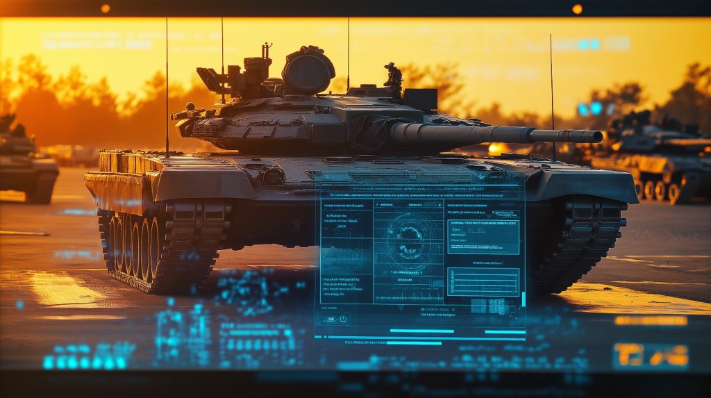
  • Military fixed-wing displays add MIL-STD-810 environmental hardening, NVIS compatibility for night-vision goggle operations, and security partitioning for classified data.
  • Rotary-wing displays must withstand extreme vibration profiles and often feature smaller form factors to fit within constrained cockpit envelopes.
  • UAV ground control station displays replicate flight deck functionality in a ground-based console, with low-latency video integration and remote pilot interface requirements.

How Cockpit Display Systems Work
Data flows into the display system from sensors and avionics subsystems over standardized data buses. The DMC processes these inputs, applies display management logic, and renders graphical pages according to the active configuration. Outputs are then driven to the display units via digital video interfaces such as DVI or LVDS. Modern systems support reconfiguration: if one display fails, the crew can redistribute its pages across remaining screens, maintaining full situational awareness. This reconfigurability is a cornerstone of cockpit display technology today, directly contributing to dispatch reliability and crew safety.

Testing Standards and Certification Requirements
Cockpit display testing is one of the most rigorous disciplines in avionics qualification. Systems must demonstrate compliance with a layered set of standards before a regulator will approve installation:

  • DO-160G (RTCA): Governs cockpit display environmental testing, covering temperature, altitude, humidity, vibration, shock, explosion-proofness, waterproofness, magnetic effect, power input, voltage spike, and lightning effects. Each test category maps to an equipment category appropriate to the installation zone.
  • MIL-STD-461 and MIL-STD-464: Electromagnetic compatibility requirements for military platforms, ensuring displays neither radiate interference nor are susceptible to the electromagnetic environment.
  • MIL-STD-810H: Defines cockpit display reliability testing under temperature extremes, altitude, humidity, vibration, shock, and other environmental stressors specific to military applications.
  • RTCA DO-178C / DO-254: Software and hardware design assurance levels (DAL A through E), required by FAA and EASA for civil-certified displays. DAL A items have no acceptable failure rate.
  • NVIS compatibility (MIL-STD-3009): Military displays that will be used with night-vision goggles must not emit wavelengths that degrade goggle performance, verified through photometric testing.

Achieving compliance with these cockpit display standards requires close collaboration between display manufacturers, platform integrators, and certification authorities from the earliest design phases.

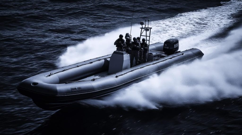
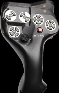
AEROMAOZ is a world-recognized supplier of rugged HMI solutions for mission-critical aviation and defense environments. With more than 45 years of design and manufacturing experience, AEROMAOZ produces illuminated panels and bezels, control sticks and grips, push-button switches, NVIS-compatible lighting systems, and ruggedized display interfaces for commercial and military aviation, armored vehicles, UAVs, naval platforms, and flight simulators. Certified to AS9100 and qualified to QPL standards, the company supplies Tier-1 system integrators and platform manufacturers worldwide. Learn more at aeromaoz.com

Future Trends in Cockpit Display Technology

Several converging technologies are reshaping the next generation of avionics display systems:

  • Large-format curved displays: Single-panel solutions that span the entire instrument panel width, reducing bezels and increasing usable screen real estate.
  • Synthetic vision and enhanced vision: Integration of terrain databases, infrared sensors, and augmented reality overlays to provide pilots with a clear forward view regardless of meteorological conditions.
  • OLED and microLED panels: Offer higher contrast ratios, wider color gamut, and reduced power consumption versus traditional LCD technology – critical for energy-constrained UAV platforms.
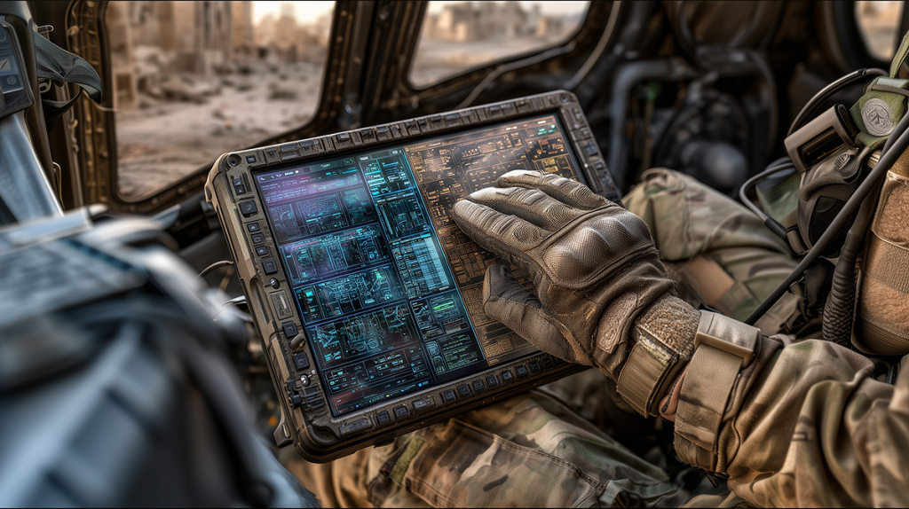
  • Touchscreen and gesture interfaces: Increasingly adopted in commercial cockpits and advanced military trainer aircraft, though glove compatibility and vibration tolerance remain engineering challenges.
  • AI-driven display management: Algorithms that adapt the display layout dynamically based on the current phase of flight, detected crew workload, and system health, reducing cognitive load at critical moments.

As platforms evolve and mission requirements become more demanding, the engineering disciplines surrounding cockpit display systems – from hardware ruggedization and environmental qualification to software assurance and human factors validation – will remain central to aviation safety and operational effectiveness. Procurement managers and design engineers specifying display solutions must balance innovation with the proven reliability standards that govern certified airborne systems.

WORTH READING /

Touch Technology Selection for Military Applications: Capacitive vs. Resistive in 2025

Touchscreen technology selection for military applications requires careful evaluation of competing technologies, balancing usability, durability, and operational requirements. Capacitive touch dominates consumer electronics through superior sensitivity and multi-touch capability but faces significant challenges in military environments. Resistive touch offers advantages for gloved operation and exposure to harsh conditions but sacrifices responsiveness and multi-touch support. In 2025, technology maturation enables informed selection based on application-specific requirements rather than consumer defaults.

Technical Considerations and Implementation
Projected capacitive (PCAP) panels detect finger position by sensing disturbances in an electrostatic field near the screen surface. This approach enables highly responsive multi-touch input with excellent optical clarity, but the technology requires a conductive object – typically bare skin or a special stylus – to register input. Standard military and flight gloves fail to trigger conventional PCAP sensors reliably, though advanced glove-mode tuning in modern controllers has partially bridged this gap. Performance under gloved use remains inconsistent across glove materials, thickness, and operating temperatures.
Resistive panels operate through physical pressure: two conductive layers make contact when the surface is depressed, completing an electrical circuit. The technology responds to any input – gloves, styluses, or blunt objects – making it inherently suited to mission environments. Trade-offs include lower optical clarity from the dual-layer construction, reduced durability under heavy sustained use, and the absence of multi-touch capability in standard implementations.

Environmental performance is a critical differentiator. Resistive panels, when properly sealed, resist false activation from water droplets, condensation, and conductive particulates. Capacitive surfaces are vulnerable to these triggers, causing spurious inputs aboard ship, in rotorcraft wash-down environments, or during sandstorm conditions. Both technologies must meet MIL-STD-810 environmental requirements, and MIL-STD-461 electromagnetic compatibility testing is mandatory for cockpit and vehicle applications where interference from avionics, radar, and communication systems can degrade touch sensor performance.
Display integration adds complexity. Touch overlays mounted on sunlight-readable displays must balance anti-reflection coating performance with mechanical durability. Bonded-lens construction – eliminating the air gap between touch panel and display – reduces parallax, improves contrast in high-ambient-light conditions, and prevents moisture ingress, but adds manufacturing cost and complicates field replacement.

Industry Best Practices
Leading military display integrators recommend application-specific testing using representative glove types, contamination scenarios, and temperature extremes rather than relying on published specifications alone. Laboratory simulations of operational conditions consistently reveal performance gaps that datasheet comparisons miss.
Hybrid configurations are gaining adoption in 2025. Advanced ruggedized displays offer selectable touch modes – switching between high-sensitivity capacitive operation for bare-finger use and pressure-based compatibility for gloved environments. This flexibility avoids committing to a single technology during the platform design phase and extends platform relevance as mission profiles evolve.
Obsolescence planning is essential for programs with 15- to 20-year service lives. Resistive technology, while proven, receives declining commercial investment as consumer electronics move entirely to capacitive solutions. Procurement specialists should verify supplier long-term production commitments or qualify alternative assemblies during initial design to mitigate future supply chain risk.

Conclusion

Selecting the right touch technology for military applications demands rigorous evaluation of gloved usability, environmental resilience, display integration, and long-term supportability – no single technology suits every platform or mission. AEROMAOZ provides ruggedized touchscreen solutions engineered for military and commercial aviation, armored vehicle, naval, and UAV applications, supporting system integrators and platform manufacturers from technology selection through full lifecycle sustainment.

WORTH READING /

The Digitized Crew Station: Why MBTs and IFVs Are Moving to Rugged Multi-Function Displays

Modern main battle tanks and infantry fighting vehicles are undergoing a quiet revolution. Decades of analog gauges, fixed-function switches, and single-purpose readouts are giving way to reconfigurable, multi-function display panels that give crews faster situational awareness and dramatically reduced cognitive load. For defense integrators, procurement officers, and platform upgrade managers, understanding this shift is essential to making the right HMI decisions today.

The Analog Legacy and Its Limits
Legacy crew stations were designed around specific sensors and weapon systems. Adding a new capability meant adding a new physical control — a knob here, an indicator there — until dashboards became dense and unintuitive. In high-stress combat conditions, that complexity costs precious seconds. Studies in military human factors consistently show that cluttered interfaces increase operator error rates, with direct consequences for mission outcomes.

The Case for Multi-Function Displays
The pivot to rugged multi-function displays for armored vehicles offers a fundamental rethink of crew ergonomics. A single reconfigurable screen can consolidate battle management data, fire control status, navigation, vehicle diagnostics, and communications into one coherent interface. The operator selects the view relevant to the current mission phase, reducing visual scanning and decision latency.
This approach mirrors the transformation already completed in military aviation, where glass cockpit technology replaced panel after panel of dedicated instruments. The ground vehicle domain is following the same path, driven by the same pressures: more data, more sensors, more decisions per minute.

Touchscreen Technology and the Glove Problem
For years, rugged touchscreen displays for military vehicles faced a practical obstacle: crew members operate in gloves, and early capacitive screens could not register touch through standard military hand protection. The solution came through advances in projected capacitive (PCAP) technology, which can now be tuned to detect gloved input reliably — delivering the intuitive swipe-and-tap experience familiar from consumer devices, but qualified for the harshest environments on earth.
Resistive touch technology remains an option where glove sensitivity is paramount, and the choice between PCAP and resistive depends on specific platform requirements. What matters is that both technologies now meet the standards demanded by modern armored vehicle programs.

Environmental Demands: Beyond the Lab
Armored vehicle crew stations impose environmental stresses that civilian display manufacturers rarely encounter. MIL-STD-810 compliance is the baseline requirement, covering temperature extremes from -40 degrees Celsius to +70 degrees Celsius, shock loads from rough terrain and blast events, continuous vibration profiles, humidity ingress, and altitude variation. Displays must survive not just one of these conditions but all of them simultaneously over a service life measured in decades.
Size, Weight, and Power (SWaP) constraints add another layer of complexity. A display that works in a laboratory integration rack may be physically incompatible with the tight geometry of an existing turret or hull. Suppliers with a track record of form-fit-function solutions are far more valuable than those offering catalog products.

The Retrofit Opportunity
New platform programs represent only a fraction of the market. The larger opportunity – and the more urgent one – lies in mid-life upgrades to existing fleets. Leopard 2 variants, M1 Abrams upgrades, Merkava modernization programs, and comparable international platforms are all active upgrade candidates. In each case, the goal is to insert modern display and control capability without structural modification to the vehicle.
This requires suppliers who can deliver IFV crew station display upgrade solutions that match the physical envelope of legacy panels, interface with existing electronic architectures, and meet current certification requirements — all on program timelines that leave little room for qualification surprises.

AEROMAOZ: Qualified from Day One

AEROMAOZ designs and manufactures rugged HMI solutions for armored vehicles, drawing on decades of qualification experience in military aviation and ground platforms. Products are developed and certified to MIL-STD-810, MIL-STD-3009, AS9100, and AS7788 QPL standards. With a customer base that includes Elbit Systems, BAE Systems, Honeywell, and Bell Textron, AEROMAOZ brings proven supplier credentials to every armored vehicle program it supports.
As platform digitization accelerates, the quality of crew station interfaces will increasingly determine operational effectiveness. The transition to rugged multi-function displays is not a future trend — it is happening now, across every major armored vehicle program worldwide.
Contact AEROMAOZ at aeromaoz.com to discuss display and HMI solutions for your armored vehicle program.

WORTH READING /

From Crisis to Strategy: Turning Component Shortages into Competitive Advantage

Introduction
Component shortages have transformed from occasional inconveniences into persistent strategic challenges for defense electronics programs. The COVID-19 pandemic exposed semiconductor supply chain vulnerabilities that extended lead times from weeks to over a year; geopolitical tensions and export restrictions on advanced semiconductors have compounded the pressure ever since. Traditional reactive approaches – waiting for availability or absorbing premium spot-market prices – no longer suffice. The organizations pulling ahead are those that have shifted from crisis management to deliberate strategy, converting shortages into competitive advantage through proactive planning, strategic supplier relationships, flexible design, and real-time supply chain visibility.

Technical Considerations and Implementation
Traditional obsolescence management operated reactively: programs learned of component discontinuations when end-of-life notices arrived, typically providing only 6-12 months to respond. Modern predictive approaches expand that window to years. Component manufacturers publish long-term roadmaps; market intelligence services track declining production volumes; semiconductor foundries announce process node transitions that signal when older designs become uneconomical. Machine learning algorithms correlate these data streams – a component showing falling sales while its manufacturer promotes a successor generation is a strong candidate for discontinuation within 12-24 months. Programs that embed predictive obsolescence reviews into design milestones catch issues during development, when mitigation is still inexpensive, rather than during production or sustainment.

Form-fit-function replacement strategies provide essential design-phase flexibility when primary components later become unavailable. Rather than treating component selections as fixed at first layout, flexible designs identify qualified alternatives from the outset: a power supply accommodating multiple voltage regulator families through a shared pad pattern, or an FPGA design abstracted in portable HDL code that compiles to multiple vendor devices. Design reviews should map the most critical long-lead components, enumerate alternatives for each, and document what design changes would enable substitution. Having those answers on record transforms a potential crisis into a managed substitution.

Modern supply chain management platforms aggregate real-time data from distributors, manufacturers, and market intelligence services, enabling programs to monitor every item in their bill-of-materials for availability trends before shortages become critical. AI-enhanced analysis extends this further – correlating fab utilization rates with future component supply, flagging single-source dependencies, and identifying components that share common substrates and therefore carry correlated shortage risk. Organizations that invest in this visibility consistently outperform peers in schedule and cost because they secure components before market prices spike.

Industry Best Practices
Transforming vendor relationships from transactional to strategic is one of the highest-return moves available to a program office. Strategic supplier partnerships deliver preferential allocation during shortages, early discontinuation notification, collaborative roadmap alignment, and direct engineering-level technical support – none of which are available to a customer whose sole engagement is a purchase order. Building these relationships requires discipline through market cycles, maintaining commitments even when competitors offer short-term price advantages. AEROMAOZ’s four decades of authorized manufacturer partnerships provide exactly this kind of preferential access when components are scarce.

Component shortages also create the conditions under which counterfeit components infiltrate supply chains. When legitimate stock is exhausted, procurement pressure mounts to accept parts from unauthorized brokers – sources that may supply refurbished, remarked, or outright fraudulent parts. Effective mitigation requires purchasing exclusively from authorized distributors with clear custody chains, combined with incoming inspection covering visual examination, X-ray analysis, electrical parametric testing, and material verification. The cost of authentication is material but trivial against the cost of a field failure caused by a counterfeit component in a mission-critical system.

Conclusion

Component shortages are a permanent feature of the defense electronics landscape, not a temporary disruption. Programs that deploy predictive obsolescence management, flexible design, supply chain visibility, strategic partnerships, and rigorous counterfeit controls maintain schedule and cost performance while less-prepared competitors absorb delays and redesign costs. The transformation demands commitment across engineering and procurement, but the return is measurable and sustained.
AEROMAOZ‘s 45 years of supply chain experience in mission-critical avionics, combined with our network of strategic supplier relationships and proven obsolescence management practices, positions us to keep your program on track through supply chain uncertainty. Contact our engineering team to discuss how our expertise can strengthen your program resilience.

WORTH READING /

What Makes a Modern Military Display?

The Defining Characteristics of Defense-Grade Screens
In environments where a fraction of a second determines a mission’s outcome, the military display is far more than a screen. Every sensor feed, system status, and tactical picture the operator will ever see must pass through it – making it the single most consequential interface on the platform. Yet not every product that carries the label deserves it. The gap between a genuine defense-grade panel and a hardened commercial screen is wide, and specifying the wrong solution carries operational risk that propagates through the entire platform lifecycle.

Clarity Where It Counts: Optical Performance
The most visible differentiator of a true military display is luminance. Sunlight glare, desert reflections, and open hatches in direct sun render conventional screens unreadable. Defense-grade panels deliver 1,500–3,000 nits sustained for cockpit applications, rising beyond 5,000 nits for open-deck naval and vehicle-mounted use. Optical bonding eliminates the internal air gap that traps reflections, measurably improving contrast ratios and reducing operator eye fatigue. Precision anti-reflective coatings and automatic luminance control complete the picture.

Built to Survive: Environmental Ruggedization
A display must perform identically after storage at -55 °C, transport at altitude, operation in blowing sand, and cleaning with chemical decontamination agents. MIL-STD-810H covers more than thirty test methods; IP67 or IP68 sealing is a baseline requirement, not a premium option. For armored vehicle and naval programs, gun-blast overpressure and shipboard shock add test axes that commercial ruggedization programs never encounter. Suppliers who have completed these qualifications carry the evidence — those who have not are asking the integrator to absorb the risk.

Owning the Night: NVIS Compatibility
NVIS compatibility is non-negotiable for any military display used in cockpits where crews wear night-vision goggles. Unfiltered LED backlights emit strongly in the 625–930 nm near-infrared band that Gen III intensifier tubes amplify, causing NVG wash-out at the worst possible moment. MIL-L-85762A Class A and B define the radiance limits — but compliance must be validated across the full temperature range, since LED emission spectra shift at cold extremes. Programs transitioning to the US Army’s ENVG-B system face stricter requirements than those qualified only against legacy AN/AVS-6 or AN/AVS-9 goggles. Learn more on our military aviation solutions page.

Silent and Shielded: EMI/EMC Performance
A military display operates inside some of the most electromagnetically intense environments on earth — active radar suites, HF communications systems, and multi-emitter warships. Meeting MIL-STD-461G and DO-160G Section 21 requires far more than conductive gaskets added at production. EMI performance is inseparable from original mechanical design: an unbroken Faraday cage, filtered power and signal lines, and driver ICs clocked to keep harmonics away from critical navigation bands such as GPS L1. Programs that exclude the display supplier from early integration design reviews routinely discover EMC gaps at system test — an expensive problem that is fully avoidable.

Command at a Touch: Gloved Interfaces
Combat gloves, flight gloves, and NBC gear eliminate the conductivity that standard capacitive sensors require — turning a touchscreen into a useless pane of glass the moment gloves go on. Solutions in current programs include high-sensitivity projected capacitive overlays tuned to glove materials, glove-agnostic resistive overlays, and hybrid designs that pair touchscreens with physical rotary encoders and function keys for eyes-off operations. For UAV ground control stations and flight simulators, large-format multi-touch enables gesture-based map interaction and concurrent multi-sensor management that reduces single-operator cognitive workload significantly.

Designed for Decades: Service Life and Obsolescence Management
A military display decision made today will shape platform capability into the 2040s. Genuine long-service-life design means LED backlights with MTBF exceeding 50,000 hours, component selection that avoids end-of-life parts within the projected service window, and modular construction allowing backlight, touch overlay, and processing module to be replaced independently. The most underrated supplier differentiator — and one procurement teams should demand documentation on before shortlisting — is a credible Diminishing Manufacturing Sources management plan. Field return data from comparable in-service programs is far more meaningful than a calculated MTBF figure on a datasheet.

Open, Modular, and Future-Ready: Architecture Standards
The FACE™ Technical Standard, the US Army’s VICTORY architecture, and the UK MOD’s Generic Vehicle Architecture all mandate standardized display subsystem interfaces — preventing vendor lock-in and enabling best-of-breed component refresh across the platform lifecycle. For display manufacturers, this means standardized form factors, COTS GPU-based graphics processing modules with published interface specifications, and avionics software certified to DO-178C DAL B or higher. For tier-1 system integrators and platform primes, open architecture compliance has moved from a desirable feature to a gate requirement. Suppliers who cannot demonstrate it are excluded before technical evaluation begins.

The Proof Is in the Program: Qualification Pedigree

Every characteristic above can be claimed in a datasheet. The question that separates suppliers is whether they can prove it. When evaluating a military display supplier, request in-service program references with platform type, part number, entry-into-service date, and fleet size. Establish whether the supplier is the original designer and manufacturer of the optics and electronics, or an assembler of third-party components — program support and obsolescence management are qualitatively different between those two models. In military aviation programs subject to type certification, a supplier with a mature change management process shortens every qualification cycle; one without that capability extends it, at the program’s expense.

AEROMAOZ (www.aeromaoz.com) is a world-recognized designer and manufacturer of rugged Human-Machine Interface solutions for mission-critical platforms. With over 40 years of experience spanning military and commercial aviation, armored vehicles, UAVs, flight simulators, and naval platforms, AEROMAOZ brings the qualification depth, in-service track record, and cross-disciplinary engineering expertise that each of these characteristics demands.

WORTH READING /

From Cockpit to Combat Boat: How Aerospace HMI Engineering Is Redefining Naval Operator Interfaces

When the IDF Navy commissioned a purpose-built mission grip for its commando assault boats, the brief was demanding: survive the sea, serve the operator and integrate with everything. AEROMAOZ delivered – and in doing so, opened a new chapter for naval HMI.

An IDF naval commando RHIB assault boat operating at speed in Mediterranean waters. AEROMAOZ’s mission grip was purpose-engineered to control weapons and visual systems aboard vessels operating in exactly these conditions.

An IDF naval commando RHIB assault boat operating at speed in Mediterranean waters. AEROMAOZ’s mission grip was purpose-engineered to control weapons and visual systems aboard vessels operating in exactly these conditions.

There is a category of engineering problem that resists off-the-shelf solutions. It sits at the intersection of physics, physiology, and operational reality, where ambient vibration never stops, where salt-laden air attacks every connector, where the operator’s hands may be wet and gloved and shaking from adrenaline, and where a control input made a fraction of a second too late can change the outcome of a mission.
Naval commando operations present precisely this challenge. And when the IDF Navy Seals decided to modernize the human-machine interface aboard their RHIB assault boats, they identified a partner whose core competence had been built in an equally unforgiving environment: aerospace.

A Requirement Written in Operational Reality
The operational brief for the IDF Navy Seals control grip was not produced in a procurement office. It was shaped on the water, through dialogue with the operators who live inside these systems. The requirements that emerged were precise and uncompromising:
Sustained operability through constant vibration, salt spray, and extreme temperature cycling
Seamless control of both weapons and visual systems from a single interface
Full NVIS (Night Vision Imaging System) compatibility to support covert night operations
Ergonomic geometry enabling confident, precise grip for several hours without operator fatigue
Co-designed with end users at every stage of development – not validated against them after the fact
What these requirements describe is not a joystick. They describe a life-safety system that must perform reliably under conditions few commercial products are designed to encounter.

Three Engineering Disciplines, One Integrated Product
AEROMAOZ’s approach to the IDF Navy Seals grip was defined by integration. Rather than treating mechanical, electrical, and ergonomic design as sequential phases, the development team converged all three disciplines from the outset – allowing trade-offs between sensor placement, structural geometry, and operator comfort to be resolved in real time rather than retrofitted at the end.
The result is a control grip whose features reflect that integrated methodology:
High-precision sensors delivering accurate input detection under dynamic sea-state conditions
Configurable button architecture supporting versatile multi-system control from a single grip
Optional force feedback providing tactile confirmation of inputs during high-intensity operations
Full NVIS compatibility across all illuminated interface elements
Contoured, lightweight ergonomic housing designed for extended wear without fatigue, even under physically demanding conditions

The AEROMAOZ mission grip developed for IDF Navy Seals assault boats, featuring multi-function rocker clusters, INT/POS switching, and full NVIS compatibility.

Critically, the design was refined continuously through direct feedback from IDF Navy Seals operators – not through representative surveys or post-development acceptance testing, but through iterative co-design embedded in the development process itself. The final product reflects actual field requirements rather than interpreted ones.

Why Aerospace Heritage Translates to Naval Performance
The leap from aerospace cockpit to naval combat boat is shorter than it might appear. Both environments impose wide thermal ranges, high mechanical shock and vibration, electromagnetic interference, and operators working under sustained physical and cognitive stress. Both require interfaces that deliver the right input to the right system with zero ambiguity, every time.

With over 45 years of experience designing and manufacturing rugged HMI solutions for military aviation, commercial aviation, armored fighting vehicles, UAV ground control stations, and flight simulation, AEROMAOZ has built its product philosophy around exactly these constraints. Every component in the company’s portfolio – control grips and sticks, rugged display panels and bezels, multi-function keypads, integrated cockpit interface units – is engineered for high-vibration, wide-temperature-range, EMI-dense environments, with full compliance to military and airworthiness certification standards.

AEROMAOZ serves tier-1 system integrators and platform manufacturers including Thales, Honeywell, Elbit Systems, BAE Systems, Boeing, Airbus, and Lockheed Martin. The design principles behind a display bezel that performs reliably in the cockpit of a commercial airliner are directly applicable to a naval vessel bridge system, a coast guard patrol craft, or an offshore platform operator console – and now, proven aboard a special operations assault boat.

A New Domain, A Familiar Methodology

The IDF Navy Seals grip program is, in one sense, a first – AEROMAOZ’s formal entry into the naval domain as a program of record. But in another and more important sense, it is simply another proof point for a methodology the company has applied across every program it has undertaken:
Deep operator co-design, embedded in the development process from day one
Multi-disciplinary engineering integration, resolving trade-offs before they become problems
Uncompromising commitment to in-field performance over lab-compliant specification
For naval procurement offices and system integrators seeking an HMI partner with verified credentials in mission-critical environments – one that brings both aerospace-grade engineering and a proven track record of operator-centered design – this program provides a clear reference point.
AEROMAOZ’s diversified portfolio – spanning panels, displays, bezels, pushbuttons, and control sticks – positions the company as a capable, experienced partner for both defense and commercial naval integrators. The aerospace heritage is intact. The naval capability is now proven.

WORTH READING /

Designing for the Extremes: Thermal Management in -40°C to +85°C Environments

Military and commercial aviation platforms operate in hostile environments-from frozen Arctic tundra at -40°C to scorching Middle Eastern deserts exceeding +85°C. Between these extremes lies a spectrum of environmental challenges: violent vibrations, corrosive salt spray in naval environments, electromagnetic interference, and extreme pressure differentials at altitude. For avionics manufacturers and system integrators, success depends on designing for the extremes.

The Temperature Challenge: Beyond Simple Heating and Cooling
Thermal management extends beyond single temperature specifications. Electronic components experience stress from absolute extremes, thermal cycling during flight transitions, and thermal gradients within enclosures. At -40°C, displays lose contrast, solder joints become brittle, lubricants solidify, and polymers lose flexibility. Battery performance degrades, capacitance shifts, and mechanical tolerances tighten. Yet systems must achieve full capability within minutes of power-up. At +85°C operational temperature, semiconductor junctions approach maximum ratings, capacitors age rapidly, and materials outgas compounds that fog optics or corrode contacts. Thermal management becomes critical for long-term reliability.

Modern thermal design employs heat sinking, conformal coating, thermal interface materials, heat pipes, or thermoelectric cooling. Most challenging is managing thermal shock-rapid transitions creating mechanical stress through differential expansion. Material selection requires compatible coefficients of thermal expansion (CTE) across dissimilar material interfaces.

DO-160: The Environmental Testing Standard
RTCA DO-160, “Environmental Conditions and Test Procedures for Airborne Equipment,” provides aviation’s definitive environmental qualification framework. Now in revision G, this standard establishes test categories spanning environmental stressors aircraft equipment encounters.
Section 4: Temperature and Altitude testing spans multiple categories. Category A1 covers -15°C to +40°C for standard installations, while Category B extends to -40°C to +55°C. Category A3 reaches +85°C operational temperature, and Category A5 tests from -55°C to +95°C for extreme installations.
Section 8: Vibration proves particularly demanding. Standard Vibration Tests (Category S) subject equipment to swept sine and random vibration representing normal aircraft operation. Robust Vibration Tests (Categories R, U, U2) simulate helicopter installations and prolonged exposure, including endurance testing stressing functional performance and structural integrity.
Sections 15-21 cover Electromagnetic Interference (EMI) and Electromagnetic Compatibility (EMC), verifying equipment neither generates interfering emissions nor succumbs to external electromagnetic fields. Testing includes conducted and radiated emissions, voltage spike susceptibility, and audio frequency conducted susceptibility.
Section 14: Salt Spray addresses naval aviation where salt-laden air corrodes structures and degrades coatings. Section 12: Sand and Dust proves critical for desert operations where particulate infiltration abrades parts, bridges contacts, and clogs thermal ventilation.

Material Science: The Foundation of Harsh Environment Design
Aluminum alloys remain the workhorse for ruggedized enclosures, offering thermal conductivity, low weight, and EMI shielding. 6061-T6 provides good strength and corrosion resistance, while 7075-T6 offers superior strength. Surface treatments-hard anodizing, chromate conversion coating-protect against corrosion.
Conformal coatings have evolved beyond moisture barriers. Modern parylene coatings provide pinhole-free protection while maintaining thermal performance. Advanced ceramics and composite materials address applications where traditional materials fail. Aluminum nitride substrates provide thermal conductivity with electrical insulation. Polyimide flexible circuits maintain reliability across extreme temperatures.
Solder technology transformed with lead-free mandates. While tin-silver-copper (SAC) alloys satisfy regulations, their brittleness and tin whisker growth create harsh environment challenges. High-reliability designs employ gold wire bonds or specialized solders for improved low-temperature performance.
Optical materials face unique challenges. Standard acrylic and polycarbonate become brittle at low temperatures. Glass remains stable but requires careful mounting. Sapphire offers ultimate hardness and temperature stability for critical elements.

Application-Specific Challenges
Naval platforms face relentless corrosion from salt spray, humidity, and temperature cycling. Designs emphasize sealed connectors with gold-plated contacts, stainless steel hardware, and multiple protective coating layers. Many naval designs employ sealed enclosures with internal pressure equalization.
Desert operations combine extreme heat, thermal cycling, and abrasive dust. Equipment exposed to direct sunlight may experience surface temperatures exceeding +100°C. Radiative heating drives reflective finishes, thermal barriers, and sometimes active cooling. Sand filtration proves critical, requiring accessible filter elements.
High-altitude operations create pressure differentials stressing sealed enclosures and affecting thermal dissipation. Convective cooling effectiveness decreases with reduced air density, potentially halving heat transfer at 40,000 feet. Designs compensate through enlarged airflow paths, heat pipes, or conduction to aircraft structure.
Arctic operations challenge materials, lubricants, and operators. Beyond low-temperature concerns, Arctic conditions create extreme differentials between heated cockpits and external mounting, ice accumulation affecting seals, and long periods at temperature extremes.

The Integration Challenge
Environmental qualification occurs within complete system integration context. A display qualified to +85°C may fail when installed in a console restricting airflow or positioned adjacent to heat-generating computers. Thermal modeling using computational fluid dynamics predicts temperature distributions, guiding vent placement, component layout, and thermal interface requirements.
Qualification testing proceeds hierarchically-components first, then assemblies, finally complete systems. This identifies problems early when correction costs remain reasonable, but demands careful attention to test conditions matching actual installations.

Conclusion

Designing for environmental extremes demands holistic understanding of thermal management, material science, environmental testing, and operational realities. The difference between systems that survive and those that excel lies in attention to details: thermal interface preparation, connector sealing, coating application, and mounting hardware selection.

With over 40 years delivering mission-critical rugged HMI solutions across military and commercial aviation, armored vehicles, UAVs, flight simulators, and naval platforms, Aeromaoz brings deep expertise in thermal management and environmental qualification. Our solutions operate reliably from frozen Arctic deployments to scorching desert operations, from sea-level naval operations to high-altitude flight, ensuring mission success across diverse and demanding environments.

WORTH READING /

AEROMAOZ to Exhibit at ILA Berlin Air Show – Visit Us at the Israeli Defense Pavilion

AEROMAOZ is proud to announce its participation in ILA Berlin Air Show 2026, one of the world’s most prestigious aerospace and defense exhibitions. We will be exhibiting as part of the Israeli Defense Industries Pavilion, showcasing our latest innovations to an international audience of aviation leaders, integrators, and platform manufacturers.


With over 40 years of engineering excellence, AEROMAOZ stands at the forefront of Rugged Human-Machine Interface (HMI) solutions – purpose-built for the demanding realities of both commercial and military aviation. Our product portfolio is designed to perform where it matters most: in mission-critical environments where crew efficiency, situational awareness, and operational reliability are non-negotiable.
At ILA Berlin, visitors will have the opportunity to explore AEROMAOZ’s cutting-edge lineup of ruggedized displays, control panels, mission grips, and smart cockpit systems – all engineered to the highest airworthiness standards, including DO-160, DO-254, MIL-STD-810, and NVIS-compatible MIL-STD-3009. Whether integrated into fixed-wing aircraft, rotorcraft, UAVs, or ground-based simulators, our HMI solutions are trusted by leading defense integrators and tier-1 suppliers.
As aviation evolves, from next-generation tiltrotors to autonomous platforms — AEROMAOZ continues to pioneer the technologies that keep operating teams in full command, in any condition, at any altitude.

Schedule a Meeting with Our Marketing Team
ILA Berlin is a unique opportunity to sit down face-to-face with us. Whether you are exploring a new platform integration, evaluating HMI suppliers, or looking to deepen an existing partnership – we invite you to book a dedicated, one-on-one briefing at our booth.

To schedule your meeting in advance, please contact us at: aeromaoz.com/contact

Slots are limited – we encourage you to reach out early and secure your preferred time.
We look forward to meeting you in Berlin.

AEROMAOZ — Rugged HMI Solutions
for the World’s Most Demanding Aviation Environments

WORTH READING /

NVIS Compatibility in 2025: Balancing Readability, Safety, and Covert Operations

In the darkness of contested airspace, military pilots navigate where the slightest cockpit illumination could compromise mission success or crew survival. Night Vision Imaging Systems (NVIS) technology has evolved from tactical advantage to operational necessity, but achieving true NVIS compatibility remains one of the most technically demanding challenges in avionics design. Understanding the nuances of MIL-STD-3009 and balancing competing requirements for visibility, safety, and operational security has never been more critical.

Understanding MIL-STD-3009: The Foundation of NVIS Design
MIL-STD-3009, which superseded MIL-L-85762A in 2001, establishes emission requirements for aircraft lighting compatible with night vision goggles (NVGs). The standard addresses a fundamental challenge: cockpit instruments must be clearly visible to the unaided eye while producing minimal emissions in wavelengths that interfere with NVGs or reveal aircraft position. The standard defines three NVIS classes based on objective lens filter characteristics:
Class A NVIS employs a 625nm minus-blue filter, the most restrictive specification. Class A systems prohibit red cockpit lighting as red wavelengths overlap with the NVG response band, designed for maximum covert operation capability.
Class B NVIS utilizes a 665nm objective lens filter with slightly relaxed restrictions permitting limited red lighting. Class B represents the most common specification for military cockpits, offering practical balance between operational flexibility and NVIS performance.
Class C NVIS, known as “leaky green,” features a notched spectral response allowing very specific red wavelengths, primarily for head-up display (HUD) applications where HUD symbols must remain visible through NVGs.

The Science of NVIS Radiance and Chromaticity
Achieving NVIS compatibility requires precise control of spectral radiance and chromaticity. Spectral radiance, measured in mW/cm², determines light energy entering NVG sensors. MIL-STD-3009 establishes maximum NVIS radiance (NRa and NRb) values by weighting spectral measurements against NVG filter response. IR emissions must fall below the lowest outside night sky radiation source to avoid interfering with the amplified image.
Chromaticity defines color quality and purity. MIL-STD-3009 specifies exact chromaticity coordinates in the CIE 1976 color space for six colors: NVIS Green A, NVIS Green B, NVIS Yellow, NVIS Red, and NVIS White. These standardized colors ensure lighting consistency across all applications. NVIS White, despite its greenish tint, provides full-spectrum illumination combining blue through green wavelengths while remaining outside the NVG response band.

Dimming Capabilities: From Full Brightness to Covert Operations
Modern military operations demand unprecedented cockpit lighting control. During daylight, displays must achieve sunlight readability exceeding 1000 cd/m². During covert nighttime operations, systems must dim to less than 1 nit to prevent light spill.
Dual-mode NVIS systems employ independent light sources spanning dramatically different brightness ranges. Day-mode backlights provide high-brightness for sunlight operation, while NVIS-compliant backlights dim continuously to 0.1 footlamberts (approximately 0.34 cd/m²)—the standard NVIS testing luminance.
This extreme dimming range—spanning five orders of magnitude—presents engineering challenges. Electronic circuits must maintain precise color temperature and spectral characteristics throughout. Advanced light-balancing techniques employ sophisticated feedback control and spectral sensing to maintain compliance.
For covert operations requiring minimal emission, operators reduce lighting to barely perceptible levels below 0.1 cd/m². Careful attention to symbol size, contrast ratios, and font design ensures critical information remains discernible at minimum illumination.

Technology Trade-offs: LED vs. Electroluminescent vs. Filament Sources
Incandescent filament lamps were the original NVIS solution, offering broad spectral emission. However, they suffer from limited lifespan (1000-5000 hours), shock susceptibility, and heat generation. While largely superseded, they remain in legacy systems and specialized applications.
Electroluminescent (EL) panels provide thin, uniform, low-power illumination ideal for backlighting. EL offers excellent shock resistance and naturally narrow spectral emissions, though lifetime and brightness limitations restrict applications to secondary lighting roles.
Light Emitting Diodes (LEDs) dominate modern NVIS cockpit lighting, offering exceptional lifespan (50,000+ hours), low power consumption, and precise spectral control. However, implementation requires careful consideration. Blue and green LEDs can exhibit naturally compatible spectral emissions but rarely meet MIL-STD-3009 chromaticity requirements without filtering. White LEDs provide broader spectral content but require filtering to eliminate near-infrared emissions.
Broadband LEDs can be filtered for any specified color coordinate, offering design flexibility but potentially losing 60-80% of generated light. Narrowband LEDs with inherently compliant emissions simplify filtering and achieve 40-50% efficiency or higher. Advanced NVIS LED designs employ engineered spectral emissions to maximize visible output while minimizing near-infrared content, reducing filtering requirements and enhancing reliability.

Next-Generation Challenges and Solutions
As Generation III+ and Generation IV NVGs achieve higher sensitivity and broader spectral response, NVIS lighting requirements grow more stringent. Enhanced sensor sensitivity means even minor infrared leakage can degrade performance or compromise covert operations.
Digital cockpits with large-format displays present particular challenges. Unlike discrete indicators, multifunction displays must maintain NVIS compatibility while presenting complex graphics and video. Advanced NVIS display technology employs specialized LED backlights, optical filtering layers, and software-controlled spectral management to achieve compliance.
Integration of augmented reality overlays and synthetic vision systems adds complexity. These systems must blend computer-generated imagery with real-world views through NVGs without introducing incompatible emissions or disrupting the visual experience.
Certification and testing for NVIS compliance demands sophisticated measurement capabilities. Spectroradiometer measurements in controlled dark room environments verify spectral radiance across relevant wavelengths at the specified 0.1 fL luminance level.

The Path Forward
As military operations increasingly rely on night vision technology, NVIS compatibility evolves from specialized requirement to fundamental design constraint. Success demands deep understanding of operational environments, human factors, and the delicate balance between competing requirements.
Organizations excelling in NVIS integration recognize that specifications represent minimum thresholds. They invest in advanced testing capabilities, maintain close relationships with operational communities, and continuously refine approaches based on real-world feedback. Most critically, they understand NVIS compatibility is an ongoing commitment to supporting operators in the world’s most demanding environments.

With over 40 years of experience in advanced HMI solutions, Aeromaoz provides complete NVIS compatibility solutions featuring sophisticated light balancing expertise across all classes and color specifications. Our rugged display systems deliver the precise dimming control, spectral performance, and operational reliability required for mission-critical military aviation platforms operating in the most challenging nighttime environments.

WORTH READING /

The Evolution of Adaptive HMI: From Supervisory Control to AI-Assisted Decision Making

The cockpit of a modern military aircraft represents one of the most complex human-machine interfaces ever conceived. What began as analog dials has evolved into sophisticated digital ecosystems where pilots interact with artificial intelligence, process multi-domain operational data, and manage increasingly autonomous systems. The global aircraft ergonomics and HMI design market, valued at $2.87 billion in 2024, is projected to reach $5.45 billion by 2033, growing at a CAGR of 7.4%—driven by the fundamental transformation of how operators interact with aviation platforms.
This evolution reflects a philosophical shift from supervisory control, where operators managed discrete systems, to AI-assisted decision making, where human judgment and machine intelligence collaborate in real-time across multiple operational domains.

From Glass Cockpits to Cognitive Partners
The transition from analog instruments to digital glass cockpits marked the first major revolution in HMI design, integrating navigation, communication, and mission systems into single platforms while reducing size, weight, and power requirements critical for military aircraft. However, early digital systems still operated on a supervisory control model—pilots input commands, systems executed them. Modern adaptive HMI systems are fundamentally different, employing machine learning algorithms to understand operator patterns, anticipate needs, and proactively present relevant information based on mission context, threat environment, and aircraft state.

Advanced head-up displays and helmet-mounted displays now project critical information directly onto pilots’ line of sight, reducing cognitive load. These systems dynamically adjust what information they present based on phase of flight, mission stage, and detected threats—the interface becomes contextually aware. AI integration extends beyond information display. Modern systems employ predictive analytics to identify potential equipment failures, optimize fuel consumption and flight paths in real-time, and recommend tactical responses to emerging threats. The cockpit evolves from a control interface into a cognitive partner augmenting human judgment with machine intelligence.

Multi-Domain Operations: The New Imperative
Future battlefields against major power adversaries demand more survivable command, control, communications, computers, intelligence, surveillance and reconnaissance capabilities. Multi-Domain Operations (MDO) represent the operational concept driving HMI evolution. MDO ensures armed forces act as a unified force capable of maneuvering across land, air, maritime, space, and cyberspace in real-time. For aviation platforms, pilots must simultaneously manage their aircraft, coordinate with ground forces, process space-based intelligence, respond to cyber threats, and integrate effects across all domains.

As MDO mission requirements expand, so do the communications, identification, navigation and survivability components integrated into platforms, each bringing integration and training requirements. Without intelligent, adaptive interfaces that synthesize this data, operator cognitive overload becomes inevitable. Modern MDO-capable cockpits employ AI-driven information fusion to address this challenge. Rather than presenting data from dozens of individual systems, adaptive HMI systems process inputs across all domains, identify patterns and threats, prioritize information based on mission context, and present synthesized intelligence through intuitive visual displays. The UH-60V Black Hawk’s upgrade from analog to digital glass cockpit specifically improves interoperability and survivability on the Multi-Domain Battlefield.

Human Factors in Autonomous Systems
The rise of autonomous and semi-autonomous systems introduces challenging human factors considerations. As aircraft operate with varying levels of autonomy—from pilot assistance to fully autonomous UAVs—the operator’s role changes from active control to supervisory management. This creates the “out-of-the-loop” problem. When systems operate autonomously for extended periods, operators lose situational awareness and struggle to regain control during anomalies. Modern cockpits present information intuitively to reduce mental strain. Adaptive HMI systems address this through human-autonomy teaming interfaces. The interface continuously communicates what autonomous systems are doing, why they’re making specific decisions, and what they’re planning next, keeping operators cognitively engaged. Gesture and voice control systems allow pilots to interact without physical controls, enhancing safety and reducing workload during critical phases. These natural interaction methods reduce the interface barrier between human intent and machine execution.

Adjustable autonomy allows operators to dynamically adjust automation levels based on mission phase, workload, and complexity. During high-workload phases, systems increase autonomy to manage routine tasks. During mission-critical decisions, operators can request more detailed information and assume direct control.

The Operator-Centric Design Philosophy
Successful adaptive HMI evolution requires unwavering commitment to operator-centric design. Technology enables capability, but human operators remain at the center of mission execution. The most sophisticated AI and automation serve operators, not replace them. This philosophy demands deep understanding of operator needs, workflows, and cognitive patterns developed through extensive operational experience. Effective HMI design requires continuous collaboration with operational communities, iterative testing in realistic scenarios, and willingness to prioritize operator effectiveness over technological elegance.

Ergonomic considerations remain fundamental. Physical layout, control accessibility, display visibility under all lighting conditions including night vision goggle compatibility, and system reliability in harsh environments directly impact operator performance. Advanced AI cannot compensate for poor ergonomic design.
The integration of touchscreen controls exemplifies this balance. Military aircraft cockpit systems increasingly adopt touchscreen controls for easier information access. However, touchscreens must maintain physical controls for critical functions requiring immediate access without visual attention.

The Path Forward

The trajectory toward fully adaptive, AI-integrated cockpit interfaces is clear, but challenges remain. Certification requirements for AI-driven systems continue evolving as regulators develop frameworks for verifying machine learning algorithms in safety-critical applications. Cybersecurity concerns grow as cockpits become more connected. Training paradigms must adapt to prepare operators for cognitive partnership with intelligent systems.
Most fundamentally, the industry must maintain focus on supporting operators in accomplishing increasingly complex objectives in contested, multi-domain environments. Technology serves this goal, but operator trust, effectiveness, and safety remain paramount. The evolution from supervisory control to AI-assisted decision making represents a fundamental reimagining of the relationship between human operators and the systems they command. As this evolution continues, organizations that thrive will combine deep technological capability with genuine understanding of operational needs, maintaining operator-centric design philosophy even as the sophistication of the human-machine interface reaches unprecedented levels.

With over 40 years of experience in HMI evolution and an unwavering operator-centric design philosophy, Aeromaoz delivers rugged display solutions and human-machine interfaces that support both current operations and next-generation adaptive systems for mission-critical military and commercial aviation platforms.